Difference between revisions of "TSL25911FN Ambient Light Sensor SKU: CQRTSL25911"
(→Download and run the test examples) |
(→Raspberry Pi Application) |
||
| (45 intermediate revisions by the same user not shown) | |||
| Line 1: | Line 1: | ||
| − | [[File: | + | [[File:CQRTSL25911_A.jpg|thumb|200px|right|Ambient Light Sensor]] |
=='''Description'''== | =='''Description'''== | ||
AMS' TSL2591 device series provides a wide 600M:1 dynamic range, up to 88,000 lux (bright sunlight), which improves design flexibility and provides engineers with ambient light sensors and a variety of non-display performance display applications. | AMS' TSL2591 device series provides a wide 600M:1 dynamic range, up to 88,000 lux (bright sunlight), which improves design flexibility and provides engineers with ambient light sensors and a variety of non-display performance display applications. | ||
| Line 8: | Line 8: | ||
CQRTSL25911 Ambient light sensor integrates TSL25911FN chip, measures infrared plus visible light (wider range than TSL2561), features 600M: 1 wide dynamic range, Detects Light Intensity up to 88000Lux (Bright Sunlight), Controlled via I2C Interface, low power consumption. It is capable of operating across various light environment. Onboard voltage translator, compatible with 3.3V/5V operating voltage, Compatible with Raspberry Pi, Arduino, STM32 and other motherboards. | CQRTSL25911 Ambient light sensor integrates TSL25911FN chip, measures infrared plus visible light (wider range than TSL2561), features 600M: 1 wide dynamic range, Detects Light Intensity up to 88000Lux (Bright Sunlight), Controlled via I2C Interface, low power consumption. It is capable of operating across various light environment. Onboard voltage translator, compatible with 3.3V/5V operating voltage, Compatible with Raspberry Pi, Arduino, STM32 and other motherboards. | ||
| + | ---- | ||
=='''Features'''== | =='''Features'''== | ||
| Line 17: | Line 18: | ||
*Onboard voltage translator, compatible with 3.3V/5V operating voltage | *Onboard voltage translator, compatible with 3.3V/5V operating voltage | ||
*Comes with development resources and manual (examples for Raspberry Pi/Arduino/STM32) | *Comes with development resources and manual (examples for Raspberry Pi/Arduino/STM32) | ||
| − | [[image: | + | [[image:CQRTSL25911_B.jpg|thumb|1000px| center]] |
---- | ---- | ||
| Line 28: | Line 29: | ||
*Dimensions: 28mm * 28mm | *Dimensions: 28mm * 28mm | ||
*Mounting hole size: 3.0mm | *Mounting hole size: 3.0mm | ||
| + | ---- | ||
| + | =='''CE Certification Documents'''== | ||
| + | [[Media:CQRTSL25911_A2407152-C05-E01 Certificate-EN 55032.pdf]] | ||
| − | + | [[Media:CQRTSL25911_A2407152-C05-R01 Report-EN55032-DC.pdf]] | |
| − | [[ | ||
---- | ---- | ||
| − | == | + | =='''Arduino Application'''== |
| − | === | + | Arduino test code |
| − | + | Special note: Before burning the program, put the TSL25911 folder in \Arduino\libraries under the compiler installation directory. Otherwise, it will not compile. For example, mine is: C:\Program Files\Arduino\libraries | |
| + | |||
| + | [[File:CQRTSL25911_Arduino-A.jpg|600px]] | ||
| + | ===Download and run the test examples=== | ||
| + | |||
| + | [[Media:CQRTSL25911_Arduino library file.rar]] | ||
| + | |||
| + | [[Media:CQRTSL25911_Arduino test code.rar]] | ||
| + | |||
<pre> | <pre> | ||
| − | + | #include "DEV_Config.h" | |
| − | + | #include "TSL2591.h" | |
| − | + | ||
| − | + | UWORD Lux = 0; | |
| − | + | void setup() { | |
| − | + | DEV_ModuleInit(); | |
| − | + | Serial.print("TSL2591_Light_Sensor\r\n"); | |
| − | + | TSL2591_Init(); | |
| − | + | } | |
| − | + | ||
| − | + | void loop() { | |
| − | + | Lux = TSL2591_Read_Lux(); | |
| − | + | Serial.print("Lux = "); | |
| − | + | Serial.print(Lux); | |
| − | + | Serial.print("\r\n\r\n"); | |
| − | + | TSL2591_SET_LuxInterrupt(50,200); | |
| − | + | } | |
| − | |||
| − | |||
| − | |||
| − | |||
| − | |||
| − | |||
| − | |||
| − | |||
| − | |||
| − | |||
| − | |||
| − | |||
</pre> | </pre> | ||
| − | + | '''Arduino test method''' | |
| − | + | ||
| − | + | Upload the test code on the Arduino board using the Arduino IDE software, connect the wires according to the wiring method, power on with the USB cable, open the serial monitor, and set the baud rate to 115200. The serial monitor displays the following data. The stronger the light intensity, the larger the data. | |
| − | + | ||
| − | + | [[File:CQRTSL25911_Arduino-B.jpg|600px]] | |
| − | | | + | ---- |
| − | |||
| − | |||
| − | |||
| − | |||
| − | |||
| − | |||
| − | |||
| − | |||
| − | |||
| + | =='''Raspberry Pi Application'''== | ||
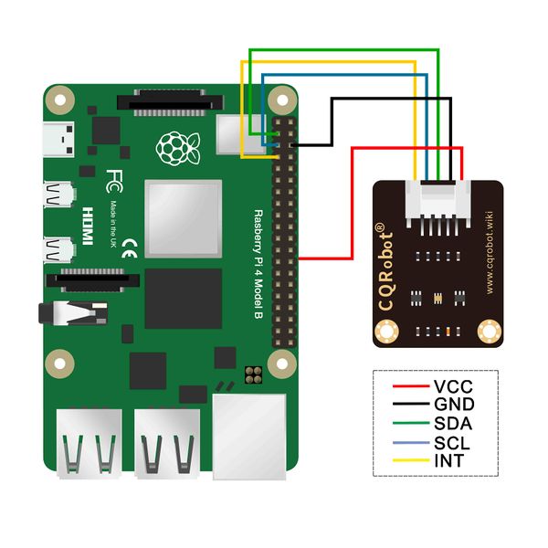
| + | [[File:CQRTSL25911_Raspberry Pi-F.jpg|600px]] | ||
===Download and run the test examples=== | ===Download and run the test examples=== | ||
| − | [[Media:CQRTSL25911_Raspberry | + | [[Media:CQRTSL25911_Raspberry Pi_Test Code-A.rar]] |
<pre> | <pre> | ||
import time | import time | ||
| Line 117: | Line 109: | ||
logging.info("ctrl + c:") | logging.info("ctrl + c:") | ||
sensor.Disable() | sensor.Disable() | ||
| − | exit()< | + | exit()</pre> |
| + | '''*1, Place the test code in a folder on the Raspberry Pi system.''' | ||
| + | |||
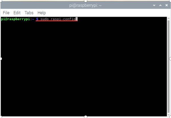
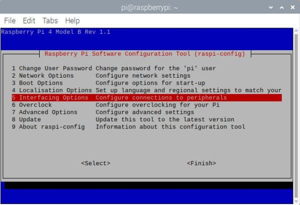
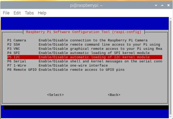
| + | '''*2, Execute sudo raspi-config in the terminal to open the Raspberry Pi I2C interface.''' | ||
| + | |||
| + | [[File:CQRTSL25911_Raspberry Pi-A.jpg|600px]] | ||
| + | |||
| + | [[File:CQRTSL25911_Raspberry Pi-B.jpg|600px]] | ||
| + | |||
| + | [[File:CQRTSL25911_Raspberry Pi-C.jpg|600px]] | ||
| + | |||
| + | [[File:CQRTSL25911_Raspberry Pi-D.jpg|600px]] | ||
| + | |||
| + | '''*3, Execute the following command in the terminal to run the program. The terminal displays the following data. The stronger the light intensity, the larger the data.''' | ||
| + | |||
| + | <pre> | ||
| + | cd TS1664 | ||
| + | ls | ||
| + | cd examples | ||
| + | sudo python main.py</pre> | ||
| + | |||
| + | |||
| + | [[File:CQRTSL25911_Raspberry Pi-E.jpg|600px]] | ||
| + | |||
| + | *Press Ctrl+C to exit the test program. | ||
| + | ---- | ||
==STM32 application== | ==STM32 application== | ||
| Line 147: | Line 164: | ||
Open the serial port assistant software on the computer and select the corresponding port to check the output data: <br/> | Open the serial port assistant software on the computer and select the corresponding port to check the output data: <br/> | ||
[[File:TSL25911 Light Sensor-9.png|600px]]<br/> | [[File:TSL25911 Light Sensor-9.png|600px]]<br/> | ||
| − | |||
| − | |||
| − | |||
| − | |||
| − | |||
| − | |||
| − | |||
| − | |||
| − | |||
| − | |||
| − | |||
| − | |||
| − | |||
| − | |||
| − | |||
| − | |||
| − | |||
| − | |||
| − | |||
| − | |||
| − | |||
| − | |||
| − | |||
| − | |||
| − | |||
| − | |||
== Resources == | == Resources == | ||
*[[Media:Light-Sensor-Schematic.pdf|Schematic]] | *[[Media:Light-Sensor-Schematic.pdf|Schematic]] | ||
| − | |||
*[[Media:TSL2591.pdf|TSL2591 Datasheet]] | *[[Media:TSL2591.pdf|TSL2591 Datasheet]] | ||
Latest revision as of 09:47, 6 May 2025
Contents
Description
AMS' TSL2591 device series provides a wide 600M:1 dynamic range, up to 88,000 lux (bright sunlight), which improves design flexibility and provides engineers with ambient light sensors and a variety of non-display performance display applications.
TSL2591 is an ultra-high sensitivity optical digital converter that can convert light intensity into digital signal output with a direct I 2 C interface. The device integrates a broadband photodiode (visible light and infrared light) and an infrared response photodiode on a single CMOS integrated circuit. Two integrating ADCs convert the photodiode current into a digital output, which represents the irradiance measured on each channel. This digital output can be input to a microprocessor, where an empirical formula is used to derive the brightness (ambient light level) in lux to approximate the response of the human eye. TSL2591 supports traditional level-style interrupts and remains valid until the firmware is cleared.
The ambient light sensor can sense the surrounding light conditions and tell the processing chip to automatically adjust the brightness of the display backlight to reduce the power consumption of the product. For example, in handheld applications such as mobile phones, notebooks, GPS and other mobile devices, the display consumes up to 30% of the total battery power, and the use of ambient light sensors can maximize the battery's working time.
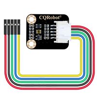
CQRTSL25911 Ambient light sensor integrates TSL25911FN chip, measures infrared plus visible light (wider range than TSL2561), features 600M: 1 wide dynamic range, Detects Light Intensity up to 88000Lux (Bright Sunlight), Controlled via I2C Interface, low power consumption. It is capable of operating across various light environment. Onboard voltage translator, compatible with 3.3V/5V operating voltage, Compatible with Raspberry Pi, Arduino, STM32 and other motherboards.
Features
- Adopts TSL25911FN, measures infrared plus visible light (wider range than TSL2561)
- Embedded ADC, direct light intensity signal output to I2C interface, less noise jamming
- High sensitivity up to 188uLux, wide dynamic range up to 600M:1
- Embedded infrared-responding photodiode, allows precise measuring even on strong infrared noise environment
- Provides interrupt output with programmable upper and lower thresholds
- Onboard voltage translator, compatible with 3.3V/5V operating voltage
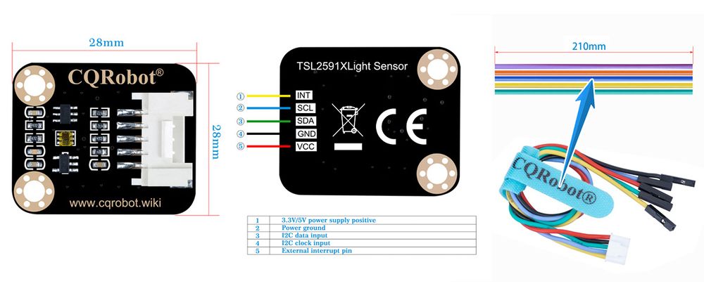
- Comes with development resources and manual (examples for Raspberry Pi/Arduino/STM32)
Specifications
- Model: CQRTSL25911
- Light sensor: TSL25911FN
- Communication interface: I2C (constant address: 0x29)
- Effective range: 0 to 88000Lux (Bright Sunlight)
- Operating voltage: 3.3V/5V
- Dimensions: 28mm * 28mm
- Mounting hole size: 3.0mm
CE Certification Documents
Media:CQRTSL25911_A2407152-C05-E01 Certificate-EN 55032.pdf
Media:CQRTSL25911_A2407152-C05-R01 Report-EN55032-DC.pdf
Arduino Application
Arduino test code Special note: Before burning the program, put the TSL25911 folder in \Arduino\libraries under the compiler installation directory. Otherwise, it will not compile. For example, mine is: C:\Program Files\Arduino\libraries
Download and run the test examples
Media:CQRTSL25911_Arduino library file.rar
Media:CQRTSL25911_Arduino test code.rar
#include "DEV_Config.h"
#include "TSL2591.h"

UWORD Lux = 0;
void setup() {
DEV_ModuleInit();
Serial.print("TSL2591_Light_Sensor\r\n");
TSL2591_Init();
}

void loop() {
    Lux = TSL2591_Read_Lux();
    Serial.print("Lux = ");
    Serial.print(Lux);
    Serial.print("\r\n\r\n");
    TSL2591_SET_LuxInterrupt(50,200);
}
Arduino test method
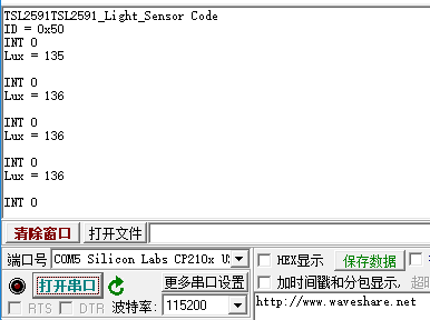
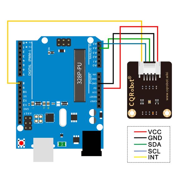
Upload the test code on the Arduino board using the Arduino IDE software, connect the wires according to the wiring method, power on with the USB cable, open the serial monitor, and set the baud rate to 115200. The serial monitor displays the following data. The stronger the light intensity, the larger the data.
Raspberry Pi Application
Download and run the test examples
Media:CQRTSL25911_Raspberry Pi_Test Code-A.rar
import time
import sys
import os

libdir = os.path.join(os.path.dirname(os.path.dirname(os.path.realpath(__file__))), 'lib')
if os.path.exists(libdir):
    sys.path.append(libdir)

import logging
from waveshare_TSL2591 import TSL2591

logging.basicConfig(level=logging.INFO)

sensor = TSL2591.TSL2591()
# sensor.SET_InterruptThreshold(0xff00, 0x0010)
try:
    while True:
        lux = sensor.Lux
        print('Lux: %d'%lux)
        sensor.TSL2591_SET_LuxInterrupt(50, 200)
        infrared = sensor.Read_Infrared
        print('Infrared light: %d'%infrared)
        visible = sensor.Read_Visible
        print('Visible light: %d'%visible)
        full_spectrum = sensor.Read_FullSpectrum
        print('Full spectrum (IR + visible) light: %d\r\n'%full_spectrum)

except KeyboardInterrupt:
    logging.info("ctrl + c:")
    sensor.Disable()
    exit()
*1, Place the test code in a folder on the Raspberry Pi system.
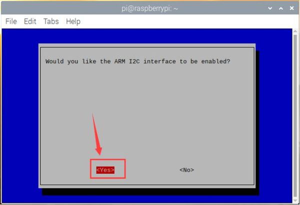
*2, Execute sudo raspi-config in the terminal to open the Raspberry Pi I2C interface.
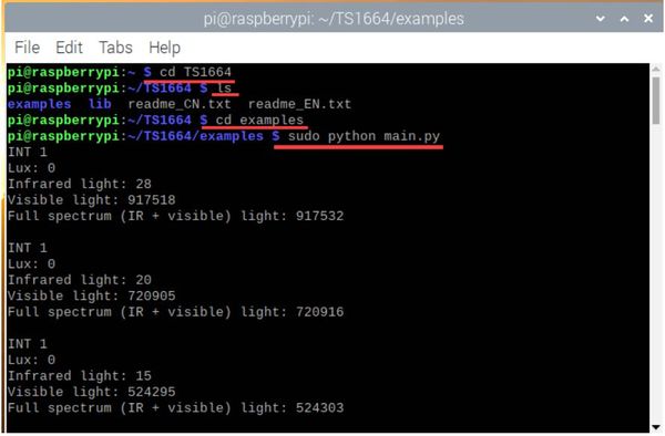
*3, Execute the following command in the terminal to run the program. The terminal displays the following data. The stronger the light intensity, the larger the data.
cd TS1664
ls
cd examples
sudo python main.py
- Press Ctrl+C to exit the test program.
STM32 application
Download the example from Waveshare Wiki and unzip it. The STM32 projects are located at the path ~/STM32/… Open \XNUCLEO-F103RB\MDK-ARM\demo.uvprojx project with Keil uVision5.
The example is based on HAL library. The development board used for the test is XNUCLEO-F103RB of Waveshare, wich chip is STM32F103RBT6.
If you want to port the examples for other STM32 chip, or change to standard libraries, you can only modify the DEV_Config.c and .h files to implement the functions and acro definitions. You can also use STM32CubeMX to port example. The example uses UART3 (PA3, PA3) to output debug information. It is set to 115200, 8N1.
Hardware connection
The connection is shown in the following table:
| TCS34725 Color Sensor | STM32 |
| VCC | 3.3V |
| GND | GND |
| SDA | SDA/D14/PB9 |
| SCL | SCL/D15/PB8 |
| INT | D8/PA9 |
Expected Result
Open the serial port assistant software on the computer and select the corresponding port to check the output data:
