Difference between revisions of "Shake Sensor"
(Created page with "thumb|300px|right|Crash Sensor =='''Introduction'''== The vibration sensor is a digital sensor that is only sensitive to one-way manual swing. Adop...") |
|||
| Line 129: | Line 129: | ||
ls | ls | ||
sudo ./TS1732 | sudo ./TS1732 | ||
| − | |||
</pre> | </pre> | ||
{|- | {|- | ||
|[[File:Shake_Sensor-5.jpg |left|800px]] | |[[File:Shake_Sensor-5.jpg |left|800px]] | ||
|} | |} | ||
Latest revision as of 07:37, 25 September 2020
Contents
Introduction
The vibration sensor is a digital sensor that is only sensitive to one-way manual swing. Adopt spring-type vibration switch, output high level when stationary, when the user shakes strongly in the specified direction once, the module outputs a low level pulse, and the onboard indicator light flashes at the same time. Thanks to the unidirectional sensitivity characteristics of the vibration switch and the corresponding filter circuit, medium-strength collisions or vibrations (such as drops, shocks) will not trigger an interrupt signal by mistake, and have strong anti-shock interference capabilities. Just shake and wave, all kinds of switch control are in your hand.
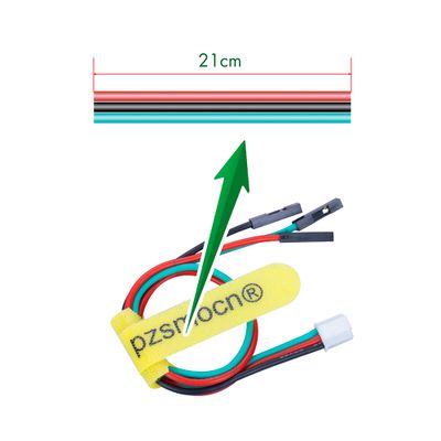
The module comes with a JST PA SMT 3-Pin buckle socket. Also, a JST PA SMT 3-Pin to DuPont female single-head wire is offered to facilitate wiring. Length: 210mm, buckle attached.
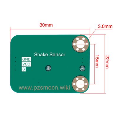
Product Size
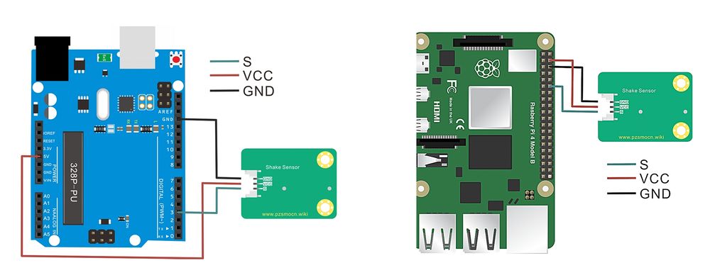
Connection Diagram
Specifications
Module
- Operating Voltage: 3.3V-5.0V
- Switch Life: more than 200,000 times
- Communication Interface: JST PA SMT 3-Pin interface
- Dimensions: 30mm * 22mm
- Fixing Hole Size: 3mm
Wire
- Withstand Voltage: <50V
- Withstand Current: <1000MA
- Length: 21CM
- Wire Sequence: Black - Negative power supply, Red - Positive power supply, Green - Digital signal output (Stand still - High level, Shaking - Low-level pulse)
Demo for Arduino
#define LED_PIN                 13
#define DIGITAL_INPUT_PIN       3             //Connect the sensor to digital Pin 3 which is Interrupts 1.

int stateFlag = 0;
unsigned long timepoint = 0;

void setup()
{
  pinMode(LED_PIN, OUTPUT);

  // Set to input mode with internal pull-up.
  // This can ensure generating intterupts under 3.3V power supply.
  pinMode(DIGITAL_INPUT_PIN, INPUT_PULLUP);

  attachInterrupt(1, toggleLED, FALLING);     // Trigger LED toggle function when the falling edge is detected
  timepoint = millis();
}
void loop()
{
  // toggle onboard LED
  if (stateFlag != 0) {
    digitalWrite(LED_PIN, HIGH);
  }
  else {
    digitalWrite(LED_PIN, LOW);
  }

}

//Interrupt serivce routinue
void toggleLED()
{
  // The hardware has done some filter.
  // To further improve stability, here add a 50ms for debouncing.
  // This will not block the main function.
  if (millis() - timepoint > 500) {
    timepoint = millis();
    stateFlag = (stateFlag + 1) % 2;
  }
}
Test Methods and Results
Wire up, upload code to Arduino board and plug in power. The ON indicator will flash once when shaking sensor once, and L indicator of Arduino board will light up or go off once.
Demo for Raspberry Pi
#include <wiringPi.h>
#include <stdio.h>

// interrupt pins
#define  btn_pin 1 // the pin of button
// interrupt flag,
int flag = 0;
//  this function will be run once interrupt happens
void blank(void){
    flag = 1;
}
int main (void)
{
    wiringPiSetup();
    pinMode(btn_pin, INPUT);
    pullUpDnControl (btn_pin, PUD_UP); // it is vital to set the interrupt pinto pull-up inout
    delay(100);
    wiringPiISR(btn_pin,INT_EDGE_FALLING,&blank);
    while(1){
        if(flag == 1){
            delay(20); // delay to eliminate the jitter of button
            if(flag == 1){
                flag = 0; // reset flag
                // LED flashes
               printf("Vibrative\n");
                delay(100);
            }
        }
    }
	return 0;
}
Test Methods and Results
1. Connect sensor to Raspberry pi 4B board, and put test code in folder way into Raspberry pi system.
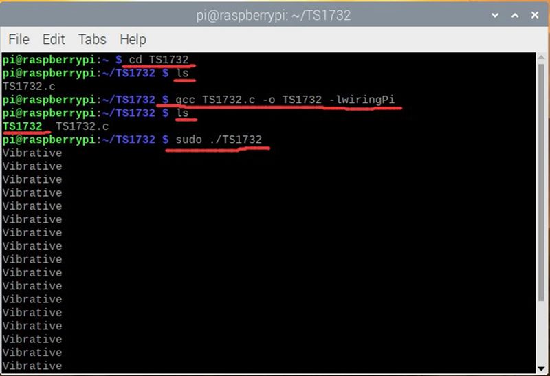
2. Execute the following command in the terminal and run the program.The ON indicator will flash once when shaking sensor once, the character Vibrative will be displayed on Raspberry pi terminal for one time and press Ctrl+C to end the program.
cd TS1732
ls
gcc TS1732.c -o TS1732 -lwiringPi
ls
sudo ./TS1732


