Difference between revisions of "Lighting String"
(Created page with "thumb|300px|right|Crash Sensor =='''Introduction'''== Remember the candlelight from childhood? In the warm light, your shadow of high and low sw...") |
(No difference)
|
Revision as of 06:44, 25 September 2020
Contents
Introduction
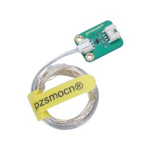
Remember the candlelight from childhood? In the warm light, your shadow of high and low swayed on the wall of the house...full of childhood memories. pzsmocn recently launched a warm-color LED light strip, imitating childhood candlelight. With the power on, the room can be filled with lights of various colors. The module supports 5V power supply, uses a transistor switch with better performance, and is equipped with a warm-color flexible light strip of 4 meters and 40 lights. The LED on the light strip displays 5 colors of white, yellow, green, blue and pink.
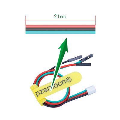
The module comes with a JST PA SMT 3-Pin buckle socket. Also, a JST PA SMT 3-Pin to DuPont female single-head wire is offered to facilitate wiring. Length: 210mm, buckle attached.
Product Size
Connection Diagram
Specifications
Module
- Operating Voltage: DC 2.5-5V (suggest 5V)
- Communication Interface: JST PA SMT 3-Pin interface
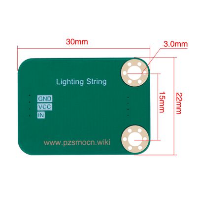
- Dimensions: 30mm * 22mm
- Fixing Hole Size: 3mm
- LED Strip: 4 meters, 40 pcs lights (white/yellow/green/blue/pink)
Wire
- Withstand Voltage: <50V
- Withstand Current: <1000MA
- Length: 21CM
- Wire Sequence: Black-Negative power supply, Red-Positive power supply, Green-Signal input
Demo for Arduino
int t;
#define  Light_string  3
void setup() {

  pinMode( Light_string, OUTPUT);
}
void loop() {

  for (t = 5; t < 255; t++ ) // turn the Light string on (HIGH is the voltage level) little and little.
  {
    analogWrite( Light_string, t);
    delay(10);
  }

  if (t >= 255)      // turn the Light string off (HIGH is the voltage level) little and little.
  {
    for (t == 255; t > 5; t--)
    {
      analogWrite( Light_string, t);
      delay(10);
    }
  }
}
Test Methods and Results
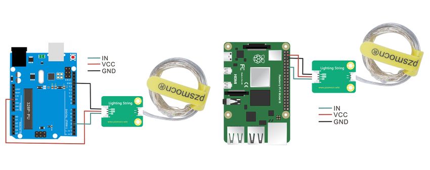
Connect according to the wiring diagram and upload the code to the arduino board. After power on, all the LEDs on the external LED strip will gradually become brighter, and then gradually become darker, alternating in cycles.
Demo for Raspberry Pi
 #include <stdio.h>
 #include <stdlib.h>
 #include <stdint.h>
 #include <wiringPi.h>
 #include <softPwm.h>

 #define LED 1

 int main(void){
     int i = 0;
          if (wiringPiSetup() == -1){
             printf("Setup GPIO error!\n");
             return -1;}
     softPwmCreate(LED, 0, 100);
          while (1){
                for (i = 0; i < 100; i++){
                     softPwmWrite(LED, i);
                     delay(10);}
                for (i = 99; i > 0; i--){
                     softPwmWrite(LED, i);
                     delay(10);}
                                    }
     return 0;
}
Test Methods and Results
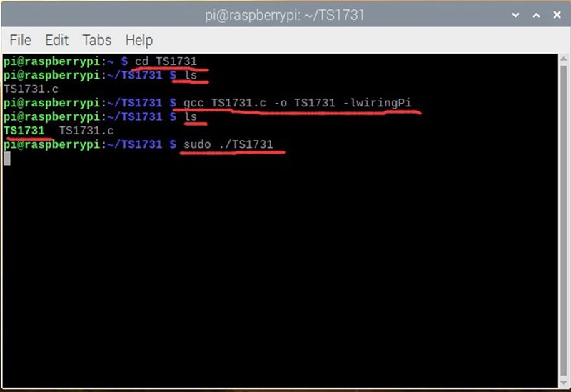
1. Connect the sensor to the Raspberry Pi 4B, and put the test code in the Raspberry Pi system in the form of a folder.
2. Execute the following commands in the terminal to run the program. We can see that all the LEDs on the external LED strips gradually become brighter, and then gradually become darker, alternating in cycles. Press Ctrl+C to stop the program.
cd TS1731
ls
gcc TS1731.c -o TS1731 -lwiringPi
ls
sudo ./TS1731
