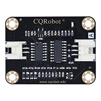
TDS (Total Dissolved Solids) Meter Sensor SKU: CQRSENTDS01
Contents
Description
TDS (Total Dissolved Solids), Chinese name Total Dissolved Solids, also known as Total Dissolved Solids, indicates how many milligrams of dissolved solids are dissolved in 1 liter of water. Generally speaking, the higher the TDS value, the more dissolved substances contained in the water and the less clean the water. Therefore, the value of TDS can be used as one of the basis for reflecting the cleanliness of water. The commonly used TDS testing equipment is a TDS pen. Although it is cheap and easy to use, it cannot transmit data to the control system for long-term online monitoring and water quality analysis. Using a special instrument, although it can transmit data and has high accuracy, it is very expensive.
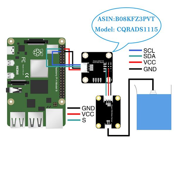
CQRobot has launched an arduino-compatible TDS sensor, which can be used to measure the TDS value of water after connecting to the arduino controller. This product is specially designed for arduino, plug and play, easy to use. 3.3V~5.5V wide voltage power supply, 0 to 2.3V analog signal output, making this product compatible with 5V and 3.3V control systems, it can be easily connected to existing control systems. With CQRobot ADS1115 16-bit AD conversion module (Model: CQRADS1115), it can accurately collect and convert analog signals to meet the compatibility requirements of the Raspberry Pi motherboard.
The excitation source for measurement uses AC signals, which can effectively prevent probe polarization, extend the life of the probe, and increase the stability of the output signal. The TDS probe is a waterproof probe that can be immersed in water for long-term measurement. This product can be applied to water quality testing in areas such as domestic water and hydroponics. With this sensor, you can easily DIY a TDS detector, easily detect the cleanliness of the water, and check your water quality.
Size Display
Specifications
Signal Transmitter Board Specifications
- Input Voltage: 3.3V to 5.5V
- Output Voltage: 0 to 2.3V
- Working Current: 3mA to 6mA
- TDS Measurement Range: 0 to 1000ppm
- TDS Measurement Accuracy: Plus/Minus 10% F.S. (25 Degree Celsius)
- Module Size: 43mm * 32.2mm
- Module Interface: JST 2.0mm 3-Pin
- Electrode Interface: JST 2.54mm 2-Pin
TDS Probe Specifications
- Number of Needle: 2
- Total Length: 83cm
- Connection Interface: JTS 2.54mm 2-Pin
- Color: Black
- Other: Waterproof Probe
Ocean Interface Cable Specifications
- Cable specifications: 22AWG
- Material: Silicone
- Withstand Voltage: Less Than 50V
- Withstand Current: Less Than 1000MA
- Length: 21cm
- Line Sequence: Black-Negative Power Supply, Red-Positive Power Supply, Green-Signal Terminal.
Connections and Examples
Attention
- The probe can not be used in water above 55 degrees centigrade.
- The probe can not be left too close to the edge of the container, otherwise it will affect the reading.
- The head and the cable of the probe are waterproof, but the connector and the signal transmitter board are not waterproof. Please be careful.
- When using the TDS instrument sensor, the sensor probe is immersed in liquid, and the purchaser needs to Separate the sensor Probe Protective Cover to avoid incorrect data reading and malfunction.
- The TDS probe cannot be used in water above 55 degrees Celsius;
- The TDS probe should not be placed too close to the edge of the container, otherwise it will affect the sensor reading parameters;
- The TDS probe head and lead are made of waterproof material and can be immersed in water, but the cable interface and signal transfer board are not waterproof, please use them carefully.
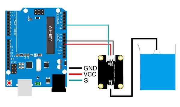
Arduino Connections
- The DuPont female single-head wiring we distribute cannot be directly connected to the UNO R3 control board. Need to be in Stack the sensor expansion board on the UNO R3 control board, or connect the male-to-male Dupont wire to the Dupont female single-head wiring(Bread Wire).
Raspberry Pi Test Code
- Compatible Raspberry Pi needs to be used with ADS1115 16-bit AD conversion module. Please refer to the specific test code: http://www.cqrobot.wiki/index.php/ADS1115_16-Bit_ADC_Module_SKU:_CQRADS1115
- Connect the module to the Raspberry Pi 4B, and put the test code in the Raspberry Pi system in the form of a folder. Dial the ADD dial switch to the 0X48 end.
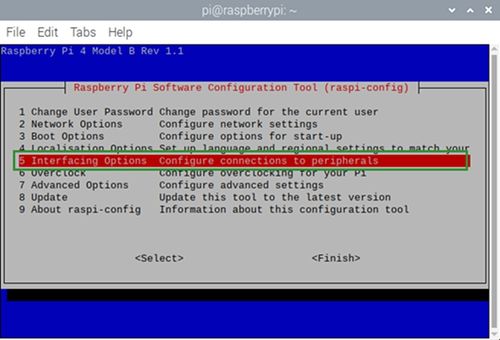
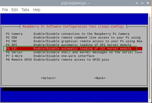
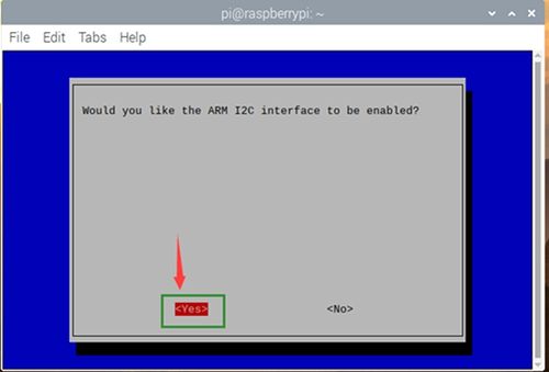
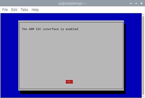
- In this experiment, the Raspberry Pi I2C communication function is used. You need to turn on the I2C function, enter sudo raspi-config in the Raspberry Pi system, and then perform the following operations.
- This kit does not include CQRobot ADS1115 16-bit AD conversion module (Model: CQRADS1115), buyers need to purchase it separately.
Arduino Application
Note: The DuPont female single-ended wiring we distribute cannot be directly connected to the UNO R3 control board. When wiring, you need to stack the sensor expansion board on the UNO R3 control board, or connect the male-to-male Dupont wire (bread wire) on the Dupont wire female single-ended wire.
Download and Run the Test Examples
Media: TDS Meter Sensor-Arduino.rar
#define TdsSensorPin A1
#define VREF 5.0      // analog reference voltage(Volt) of the ADC
#define SCOUNT  30           // sum of sample point
int analogBuffer[SCOUNT];    // store the analog value in the array, read from ADC
int analogBufferTemp[SCOUNT];
int analogBufferIndex = 0, copyIndex = 0;
float averageVoltage = 0, tdsValue = 0, temperature = 25;

void setup()
{
  Serial.begin(115200);
  pinMode(TdsSensorPin, INPUT);
}

void loop()
{
  static unsigned long analogSampleTimepoint = millis();
  if (millis() - analogSampleTimepoint > 40U)  //every 40 milliseconds,read the analog value from the ADC
  {
    analogSampleTimepoint = millis();
    analogBuffer[analogBufferIndex] = analogRead(TdsSensorPin);    //read the analog value and store into the buffer
    analogBufferIndex++;
    if (analogBufferIndex == SCOUNT)
      analogBufferIndex = 0;
  }
  static unsigned long printTimepoint = millis();
  if (millis() - printTimepoint > 800U)
  {
    printTimepoint = millis();
    for (copyIndex = 0; copyIndex < SCOUNT; copyIndex++)
      analogBufferTemp[copyIndex] = analogBuffer[copyIndex];
    averageVoltage = getMedianNum(analogBufferTemp, SCOUNT) * (float)VREF / 1024.0; // read the analog value more stable by the median filtering algorithm, and convert to voltage value
    float compensationCoefficient = 1.0 + 0.02 * (temperature - 25.0); //temperature compensation formula: fFinalResult(25^C) = fFinalResult(current)/(1.0+0.02*(fTP-25.0));
    float compensationVolatge = averageVoltage / compensationCoefficient; //temperature compensation
    tdsValue = (133.42 * compensationVolatge * compensationVolatge * compensationVolatge - 255.86 * compensationVolatge * compensationVolatge + 857.39 * compensationVolatge) * 0.5; //convert voltage value to tds value
    //Serial.print("voltage:");
    //Serial.print(averageVoltage,2);
    //Serial.print("V   ");
    Serial.print("TDS----Value:");
    Serial.print(tdsValue, 0);
    Serial.println("ppm");
  }
}
int getMedianNum(int bArray[], int iFilterLen)
{
  int bTab[iFilterLen];
  for (byte i = 0; i < iFilterLen; i++)
    bTab[i] = bArray[i];
  int i, j, bTemp;
  for (j = 0; j < iFilterLen - 1; j++)
  {
    for (i = 0; i < iFilterLen - j - 1; i++)
    {
      if (bTab[i] > bTab[i + 1])
      {
        bTemp = bTab[i];
        bTab[i] = bTab[i + 1];
        bTab[i + 1] = bTemp;
      }
    }
  }
  if ((iFilterLen & 1) > 0)
    bTemp = bTab[(iFilterLen - 1) / 2];
  else
    bTemp = (bTab[iFilterLen / 2] + bTab[iFilterLen / 2 - 1]) / 2;
  return bTemp;
}
Test Results
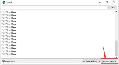
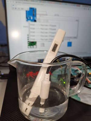
Connect according to the wiring diagram, upload the code on the arduino board, after power-on, open the serial monitor, set the baud rate to 115200, insert the TDS probe into the water to be measured, stir a few times, and observe the value printed on the serial monitor, This value is the TDS value of water. As shown below.
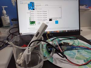
TDS Meter Sensor vs. Xiaomi Water Quality Test Pen
This is a sample of tap water from the urban pipe network.
TDS value of Xiaomi's test pen: 84 ppm
TDS value of our sensor: 92 ppm
The test result is only responsible for the sample, but you can serve as a reference.
Raspberry Pi Application
Download and Run the Test Examples
Media: TDS Meter Sensor-Raspberry Pi-New.zip
- 1. Connect the module to the Raspberry Pi 4B, and put the test code on the Raspberry Pi system in the form of a folder. Dial the ADD DIP switch to the 0X48 end.
- 2. The Raspberry Pi I2C communication function is used in this experiment. It is necessary to turn on the I2C function, enter sudo raspi-config in the Raspberry Pi system, and then perform the following operations.
- 3. Note: When wiring, connect to A1 according to the tutorial.
File: CQRobot_ADS1115.py
import smbus
import time

# Get I2C bus
bus = smbus.SMBus(1)

# I2C address of the device
ADS1115_IIC_ADDRESS0				= 0x48
ADS1115_IIC_ADDRESS1				= 0x49

# ADS1115 Register Map
ADS1115_REG_POINTER_CONVERT			= 0x00 # Conversion register
ADS1115_REG_POINTER_CONFIG			= 0x01 # Configuration register
ADS1115_REG_POINTER_LOWTHRESH		= 0x02 # Lo_thresh register
ADS1115_REG_POINTER_HITHRESH		= 0x03 # Hi_thresh register

# ADS1115 Configuration Register
ADS1115_REG_CONFIG_OS_NOEFFECT		= 0x00 # No effect
ADS1115_REG_CONFIG_OS_SINGLE		= 0x80 # Begin a single conversion
ADS1115_REG_CONFIG_MUX_DIFF_0_1		= 0x00 # Differential P = AIN0, N = AIN1 (default)
ADS1115_REG_CONFIG_MUX_DIFF_0_3		= 0x10 # Differential P = AIN0, N = AIN3
ADS1115_REG_CONFIG_MUX_DIFF_1_3		= 0x20 # Differential P = AIN1, N = AIN3
ADS1115_REG_CONFIG_MUX_DIFF_2_3		= 0x30 # Differential P = AIN2, N = AIN3
ADS1115_REG_CONFIG_MUX_SINGLE_0		= 0x40 # Single-ended P = AIN0, N = GND
ADS1115_REG_CONFIG_MUX_SINGLE_1		= 0x50 # Single-ended P = AIN1, N = GND
ADS1115_REG_CONFIG_MUX_SINGLE_2		= 0x60 # Single-ended P = AIN2, N = GND
ADS1115_REG_CONFIG_MUX_SINGLE_3		= 0x70 # Single-ended P = AIN3, N = GND
ADS1115_REG_CONFIG_PGA_6_144V		= 0x00 # +/-6.144V range = Gain 2/3
ADS1115_REG_CONFIG_PGA_4_096V		= 0x02 # +/-4.096V range = Gain 1
ADS1115_REG_CONFIG_PGA_2_048V		= 0x04 # +/-2.048V range = Gain 2 (default)
ADS1115_REG_CONFIG_PGA_1_024V		= 0x06 # +/-1.024V range = Gain 4
ADS1115_REG_CONFIG_PGA_0_512V		= 0x08 # +/-0.512V range = Gain 8
ADS1115_REG_CONFIG_PGA_0_256V		= 0x0A # +/-0.256V range = Gain 16
ADS1115_REG_CONFIG_MODE_CONTIN		= 0x00 # Continuous conversion mode
ADS1115_REG_CONFIG_MODE_SINGLE		= 0x01 # Power-down single-shot mode (default)
ADS1115_REG_CONFIG_DR_8SPS			= 0x00 # 8 samples per second
ADS1115_REG_CONFIG_DR_16SPS			= 0x20 # 16 samples per second
ADS1115_REG_CONFIG_DR_32SPS			= 0x40 # 32 samples per second
ADS1115_REG_CONFIG_DR_64SPS			= 0x60 # 64 samples per second
ADS1115_REG_CONFIG_DR_128SPS		= 0x80 # 128 samples per second (default)
ADS1115_REG_CONFIG_DR_250SPS		= 0xA0 # 250 samples per second
ADS1115_REG_CONFIG_DR_475SPS		= 0xC0 # 475 samples per second
ADS1115_REG_CONFIG_DR_860SPS		= 0xE0 # 860 samples per second
ADS1115_REG_CONFIG_CMODE_TRAD		= 0x00 # Traditional comparator with hysteresis (default)
ADS1115_REG_CONFIG_CMODE_WINDOW		= 0x10 # Window comparator
ADS1115_REG_CONFIG_CPOL_ACTVLOW		= 0x00 # ALERT/RDY pin is low when active (default)
ADS1115_REG_CONFIG_CPOL_ACTVHI		= 0x08 # ALERT/RDY pin is high when active
ADS1115_REG_CONFIG_CLAT_NONLAT		= 0x00 # Non-latching comparator (default)
ADS1115_REG_CONFIG_CLAT_LATCH		= 0x04 # Latching comparator
ADS1115_REG_CONFIG_CQUE_1CONV		= 0x00 # Assert ALERT/RDY after one conversions
ADS1115_REG_CONFIG_CQUE_2CONV		= 0x01 # Assert ALERT/RDY after two conversions
ADS1115_REG_CONFIG_CQUE_4CONV		= 0x02 # Assert ALERT/RDY after four conversions
ADS1115_REG_CONFIG_CQUE_NONE		= 0x03 # Disable the comparator and put ALERT/RDY in high state (default)

mygain=0x02
coefficient=0.125
addr_G=ADS1115_IIC_ADDRESS0
class ADS1115():
	def setGain(self,gain):
		global mygain
		global coefficient
		mygain=gain
		if mygain == ADS1115_REG_CONFIG_PGA_6_144V:
			coefficient = 0.1875
		elif mygain == ADS1115_REG_CONFIG_PGA_4_096V:
			coefficient = 0.125
		elif mygain == ADS1115_REG_CONFIG_PGA_2_048V:
			coefficient = 0.0625
		elif mygain == ADS1115_REG_CONFIG_PGA_1_024V:
			coefficient = 0.03125
		elif mygain == ADS1115_REG_CONFIG_PGA_0_512V:
			coefficient = 0.015625
		elif  mygain == ADS1115_REG_CONFIG_PGA_0_256V:
			coefficient = 0.0078125
		else:
			coefficient = 0.125
	def setAddr_ADS1115(self,addr):
		global addr_G
		addr_G=addr
	def setChannel(self,channel):
		global mygain
		"""Select the Channel user want to use from 0-3
		For Single-ended Output
		0 : AINP = AIN0 and AINN = GND
		1 : AINP = AIN1 and AINN = GND
		2 : AINP = AIN2 and AINN = GND
		3 : AINP = AIN3 and AINN = GND
		For Differential Output
		0 : AINP = AIN0 and AINN = AIN1
		1 : AINP = AIN0 and AINN = AIN3
		2 : AINP = AIN1 and AINN = AIN3
		3 : AINP = AIN2 and AINN = AIN3"""
		self.channel = channel
		while self.channel > 3 :
			self.channel = 0

		return self.channel

	def setSingle(self):
		global addr_G
		if self.channel == 0:
			CONFIG_REG = [ADS1115_REG_CONFIG_OS_SINGLE | ADS1115_REG_CONFIG_MUX_SINGLE_0 | mygain | ADS1115_REG_CONFIG_MODE_CONTIN, ADS1115_REG_CONFIG_DR_128SPS | ADS1115_REG_CONFIG_CQUE_NONE]
		elif self.channel == 1:
			CONFIG_REG = [ADS1115_REG_CONFIG_OS_SINGLE | ADS1115_REG_CONFIG_MUX_SINGLE_1 | mygain | ADS1115_REG_CONFIG_MODE_CONTIN, ADS1115_REG_CONFIG_DR_128SPS | ADS1115_REG_CONFIG_CQUE_NONE]
		elif self.channel == 2:
			CONFIG_REG = [ADS1115_REG_CONFIG_OS_SINGLE | ADS1115_REG_CONFIG_MUX_SINGLE_2 | mygain | ADS1115_REG_CONFIG_MODE_CONTIN, ADS1115_REG_CONFIG_DR_128SPS | ADS1115_REG_CONFIG_CQUE_NONE]
		elif self.channel == 3:
			CONFIG_REG = [ADS1115_REG_CONFIG_OS_SINGLE | ADS1115_REG_CONFIG_MUX_SINGLE_3 | mygain | ADS1115_REG_CONFIG_MODE_CONTIN, ADS1115_REG_CONFIG_DR_128SPS | ADS1115_REG_CONFIG_CQUE_NONE]

		bus.write_i2c_block_data(addr_G, ADS1115_REG_POINTER_CONFIG, CONFIG_REG)

	def setDifferential(self):
		global addr_G
		if self.channel == 0:
			CONFIG_REG = [ADS1115_REG_CONFIG_OS_SINGLE | ADS1115_REG_CONFIG_MUX_DIFF_0_1 | mygain | ADS1115_REG_CONFIG_MODE_CONTIN, ADS1115_REG_CONFIG_DR_128SPS | ADS1115_REG_CONFIG_CQUE_NONE]
		elif self.channel == 1:
			CONFIG_REG = [ADS1115_REG_CONFIG_OS_SINGLE | ADS1115_REG_CONFIG_MUX_DIFF_0_3 | mygain | ADS1115_REG_CONFIG_MODE_CONTIN, ADS1115_REG_CONFIG_DR_128SPS | ADS1115_REG_CONFIG_CQUE_NONE]
		elif self.channel == 2:
			CONFIG_REG = [ADS1115_REG_CONFIG_OS_SINGLE | ADS1115_REG_CONFIG_MUX_DIFF_1_3 | mygain | ADS1115_REG_CONFIG_MODE_CONTIN, ADS1115_REG_CONFIG_DR_128SPS | ADS1115_REG_CONFIG_CQUE_NONE]
		elif self.channel == 3:
			CONFIG_REG = [ADS1115_REG_CONFIG_OS_SINGLE | ADS1115_REG_CONFIG_MUX_DIFF_2_3 | mygain | ADS1115_REG_CONFIG_MODE_CONTIN, ADS1115_REG_CONFIG_DR_128SPS | ADS1115_REG_CONFIG_CQUE_NONE]

		bus.write_i2c_block_data(addr_G, ADS1115_REG_POINTER_CONFIG, CONFIG_REG)

	def readValue(self):
		"""Read data back from ADS1115_REG_POINTER_CONVERT(0x00), 2 bytes
		raw_adc MSB, raw_adc LSB"""
		global coefficient
		global addr_G
		data = bus.read_i2c_block_data(addr_G, ADS1115_REG_POINTER_CONVERT, 2)

		# Convert the data
		raw_adc = data[0] * 256 + data[1]

		if raw_adc > 32767:
			raw_adc -= 65535
		raw_adc = int(float(raw_adc)*coefficient)
		return {'r' : raw_adc}

	def readVoltage(self,channel):
		self.setChannel(channel)
		self.setSingle()
		time.sleep(0.1)
		return self.readValue()

	def ComparatorVoltage(self,channel):
		self.setChannel(channel)
		self.setDifferential()
		time.sleep(0.1)
		return self.readValue()
File: ADS1115_ReadVoltage.py
import sys
sys.path.append('../')
import time
from CQRobot_ADS1115 import ADS1115
ADS1115_REG_CONFIG_PGA_6_144V        = 0x00 # 6.144V range = Gain 2/3
ADS1115_REG_CONFIG_PGA_4_096V        = 0x02 # 4.096V range = Gain 1
ADS1115_REG_CONFIG_PGA_2_048V        = 0x04 # 2.048V range = Gain 2 (default)
ADS1115_REG_CONFIG_PGA_1_024V        = 0x06 # 1.024V range = Gain 4
ADS1115_REG_CONFIG_PGA_0_512V        = 0x08 # 0.512V range = Gain 8
ADS1115_REG_CONFIG_PGA_0_256V        = 0x0A # 0.256V range = Gain 16
ads1115 = ADS1115()
#Set the IIC address
ads1115.setAddr_ADS1115(0x48)
#Sets the gain and input voltage range.
ads1115.setGain(ADS1115_REG_CONFIG_PGA_6_144V)

VREF = 5.0
analogBuffer = [0,0,0,0,0,0,0,0,0,0,0,0,0,0,0,0,0,0,0,0,0,0,0,0,0,0,0,0,0,0]
analogBufferTemp = [0,0,0,0,0,0,0,0,0,0,0,0,0,0,0,0,0,0,0,0,0,0,0,0,0,0,0,0,0,0]
analogBufferIndex = 0
copyIndex = 0
averageVoltage = 0
tdsValue = 0
temperature = 25

def getMedianNum(iFilterLen):
	global analogBufferTemp
	bTemp = 0.0
	for j in range(iFilterLen-1):
		for i in range(iFilterLen-j-1):
			if analogBufferTemp[i] > analogBufferTemp[i+1]:
				bTemp = analogBufferTemp[i]
				analogBufferTemp[i] = analogBufferTemp[i+1]
				analogBufferTemp[i+1] = bTemp
	if iFilterLen & 1 > 0:
		bTemp = analogBufferTemp[(iFilterLen - 1)/2]
	else:
		bTemp = (analogBufferTemp[iFilterLen / 2] + analogBufferTemp[iFilterLen / 2 - 1]) / 2
	return float(bTemp)

analogSampleTimepoint = time.time()
printTimepoint = time.time()
while True :
	if time.time() - analogSampleTimepoint > 0.04:
		#print(" test.......... ")
		analogSampleTimepoint = time.time()
		analogBuffer[analogBufferIndex] = ads1115.readVoltage(1)['r']
		analogBufferIndex = analogBufferIndex + 1
		if analogBufferIndex == 30:
			analogBufferIndex = 0

	if time.time()-printTimepoint > 0.8:
		#print(" test ")
		printTimepoint = time.time()
		for copyIndex in range(30):
			analogBufferTemp[copyIndex] = ads1115.readVoltage(1)['r']
		print(" A1:%dmV "%getMedianNum(30))
		averageVoltage = getMedianNum(30) * (VREF / 1024.0)
		compensationCoefficient = 1.0 + 0.02 * (temperature - 25.0)
		compensationVolatge = averageVoltage / compensationCoefficient
		tdsValue = (133.42 * compensationVolatge * compensationVolatge * compensationVolatge - 255.86 * compensationVolatge * compensationVolatge + 857.39 * compensationVolatge) * 0.5
		print(" A1:%dppm "%tdsValue)
Run the code
Note: Make sure that the I2C address from its default (0x48);
Note: Enable "Interfacing Options - P5 I2C" by typing the below command in the terminal:
sudo raspi-config
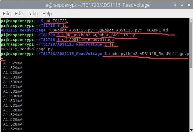
Run the code:
cd TS1728
ls
sudo python3 CQRobot_ADS1115.py
cd ADS1115_ReadVoltage
ls
sudo python3 ADS1115_ReadVoltage.py
