5.8GHz Doppler Effect Microwave Motion Sensor SKU: CQRSENWB02
Description
The microwave motion sensor is a microwave moving object detector which is designed according to the principle of Doppler Radar. This differs from the method used by a regular infrared (IR) sensor as microwave is sensitive to a variety of objects that are microwave-reflective, and its sensor readings are not affected by the ambient temperature.
Comparison with IR Sensor:
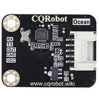
CQRobot launches 5.8GHz Doppler effect microwave motion sensor (CQRSENWB02), built-in sensor - AT5820 microwave radar chip. The AT5820 chip integrates a high-performance microwave radar transceiver and MCU, which can be interconnected with other main controllers or sensors, and filter out clutter interference through algorithms. It is not only widely used in human body detection, but also widely used in the detection of many other objects. With the characteristics of long distance and high sensitivity, it is not limited by the ambient temperature. It is used in industry, transportation, industry, agriculture, smart home, security monitoring and other fields.
The detection objects of the microwave sensor are universal. When it comes to the actual use in life, we will usually match it with another sensor for targeted detection. For example, a combination of microwave sensor and infrared pyroelectric sensor. It can accurately judge whether someone is passing by without being disturbed by sunlight and clothing color, and will not react to other objects.
Attention
There is an ultra-high frequency MOS device inside the microwave motion sensor. When you are testing, please use battery power as much as possible to avoid breakdown that is caused by the static voltage difference between the power supply and the test equipment, such as an oscilloscope.
In addition, we suggest that you use battery power to ensure the best detection effect when you are operating the product.
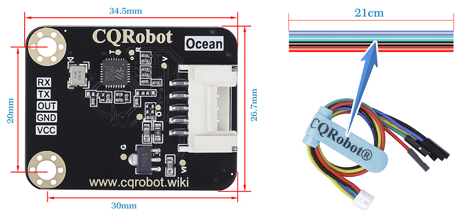
Size Display
Specifications
5.8GHz Doppler Effect Microwave Motion Sensor
- Working Voltage: DC5V
- Operating Frequency: 5.8GHz
- Radar Main Chip: AT5820
- Transmit Power: -5dBm to 0dBm
- Power Consumption: 33mA
- Baud Rate: 115200bps
- Beam Angle: 120 Degrees
- Operating Temperature: -40 Degree Celsius to +85 Degree Celsius
- Output Signal: High and Low Level or PWM
- Communication Interface: UART Serial Port
- Detection Distance: Indoor Hanging Height 3 Meters, Sensing Radius 5 Meters
- Dimension: 34.5mm * 26.7mm
- Mounting hole size: 3.0mm
Ocean Wire Specifications
- Cable Specifications: 22AWG
- Material: Silicone
- Withstand Voltage: Less Than 50V
- Withstand Current: Less Than 1000MA
- Length: 21cm
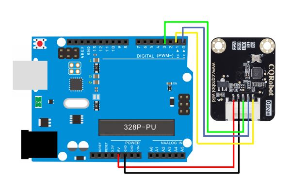
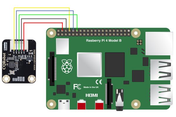
- Line Sequence: Red-VCC, Black-GND, Green-OUT, Blue-TX, Yellow-RX.
AT5820 Overview
The 5.8GHz radar SOC chip supports communication with the HOST through the UART interface, including program download, command control and debugging instructions. This article mainly introduces the communication protocol format of AT5820 and the description of each command.
Communication protocol definition
The frame data of the communication protocol is mainly divided into control frame data and reply frame data. The control frame is the frame data format of the control command sent by the host computer to the AT5820 SOC, and the reply frame is the reply to the host computer after the AT5820 SOC executes the command controlled by the host computer. Frame data format. The detailed frame data format is described below.
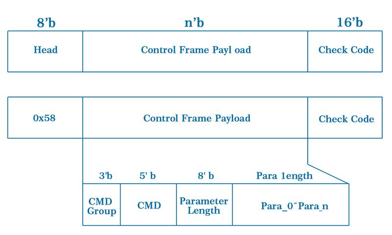
1.1 Control frame data format
The control frame is mainly the control frame data sent by the host computer to the AT5820 chip through UART, and its format is defined as follows:
Description:
- Head: Control frame header, the value is 0x58;
- Control Frame Payload: Control frame payload, divided into command packet, control command, parameter length and parameters:
- CMD Group: command grouping, 3 effective bits, supports up to 7 grouped commands;
- CMD: Control command, 5 effective bits, that is, a group supports up to 32 control commands;
- Parameter Length: the total length of the parameter (bytes);
- Para_0 ~ Para_n: Parameters (the length is specified by Parameter Length)
- Check Code: check code, the value is the sum of the previous data:
- Check Code = Head + Payload_0 + ... + Payload_n
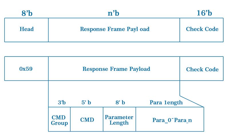
1.2 Reply frame data format
The reply data after the SOC chip executes the control command, the reply data frame format is defined as follows:
2. Command description
2.1 Set motion sensing distance
- Command code: 0x2
- Parameters: para1: distance level 0 - 31
- Send command format (HEX): 58 02 01 xx xx xx
- Reply frame: refer to reply frame format
e.g., set distance level to 15
HEX is: 58 02 01 0F 6A 00
Resp: 59 02 01 00 5C 00 (success), Other: fail
2.2 Get motion sensing distance
- Command code: 0x3
- Parameters: none
- Send command format (HEX): 58 03 00 5B 00
- Reply frame: 59 03 01 0F 6C 00 // e.g. get distance level: 15
2.3 Set the lighting time
- Command code: 0x4
- Parameters: para1: time(low byte), para2: time(high byte). In seconds.
- Send command format (HEX): 58 04 02 xx xx xx xx
- Reply frame: refer to reply frame format
e.g., set time to 1s
HEX is: 58 04 02 01 00 5F 00
Resp: 59 04 01 00 5E 00 (success), Other: fail
2.4 Get the lighting time
- Command code: 0x5
- Parameters: none
- Send command format (HEX): 58 05 00 5D 00
- Reply frame: 59 05 02 01 00 61 00 // e.g. get lot: 0x0001 (1s)
2.5 Set motion detection delta value
- Code: 0xd3
- Parameters: 16-bits, para1: delta(low byte), para2: delta(high byte).
- Send command format (HEX): 58 d2 02 xx xx xx xx
- Reply frame: refer to reply frame format
e.g., set delta to 300
HEX is: 58 d2 02 2c 01 59 01
Resp: 59 D2 01 00 2C 01
2.6 Get motion detection delta value
- Command code: 0xd4
- Parameters: none
- Send command format (HEX): 58 d3 00 2b 01
- Reply frame: 59 D3 02 2C 01 5B 01 // e.g. get delta, return value: 300
2.7 Turn on/off the light
- Command code: 0xA
- Parameters: para1: 0x1 (turn on the light), 0x0 (turn off the light)
- Send command format (HEX): 58 0A 01 01 64 00 (turn on the light); 58 0A 01 00 63 00 (turn off the light)
- Reply frame: 59 0A 01 00 64 00 (success), Other: fail
2.8 Turn on/off the radar
- Command code: 0xD1
- Parameters: para1: 0x1 (open radar), 0x0 (close radar)
- Send command format (HEX): 58 D1 01 01 2B 01 (open radar); 58 D1 01 00 2A 01 (close radar)
- Reply frame: 59 D1 01 00 2B 01 (success), Other: fail
2.9 Obtain the status of the radar switch
- Command code: 0xD0
- Parameters: none
- Send command format (HEX): 58 D0 00 28 01
- Reply frame:
59 D0 01 01 2B 01
// e.g., radar is on
59 D0 00 01 2A 01
// e.g., radar is off
2.10 Save Radar Settings
Mainly save the set parameters (sensing distance, lighting time and photosensitive threshold) in the module’s Flash, restart The machine will load the parameter value set last time.
- Command code: 0x8
- Parameters: para1: 0x1 (save), 0x0 (not save)
- Send command format (HEX): 58 08 01 01 62 00 (save),58 08 01 00 61 00 (do not save)
- Reply frame: 59 D8 01 00 62 00 (success) Other: fail
Note: If you need to save the parameters in the radar module, it is recommended to delay more than 1 second after sending the command before sending other commands.
2.11 Get Radar Saved Status
- Command code: 0x9
- Parameters: none
- Send command format (HEX): 58 09 00 61 00
- Reply frame:
59 09 01 01 64 00
// e.g., save is on
59 09 01 00 63 00
// e.g., save is off
2.12 System Reset
Command code: 0x13 Parameters: para1: reset mode (uint8) Control frame format definition:
boot_hci_ctrl_frm_t send_frm =
{ 0x58,
BOOT_HCI_SYS_RESET&0x1f,
(BOOT_HCI_SYS_RESET>>5)&0x07,
0x1,
NULL,
0x0,
};
Reply frame: The data format is as follows:
e.g., sys_reset(0x1)
HEX is: 58 13 01 01 6d 00
3. Debug command
The debugging commands are mainly used for AT5820 debugging.
3.1 Register Write
- Command code: 0x0
- Parameters: para1: 32-bits register address, para2: 32-bits data to write
- Return: 8-bits value, 0: success, other: fail.
- Send command format (HEX): 58 00 08 xx xx xx xx xx xx xx xx xx xx
- Reply frame: refer to reply frame format
e.g. reg_write(0x40003008, 0x0e810f3b)
HEX is: 58 00 08 08 30 00 40 3b 0f 81 0e b1 01
Resp: 59 00 01 00 5a 00
3.2 Register Read
- Command code: 0x1
- Parameters: para1: 32-bits register address
- Return: 32-bits register value
- Send command format (HEX): xx
- Reply frame: refer to reply frame format
e.g.reg_read(0x40003008)
HEX is: 58 01 04 08 30 00 40 D5 00
Resp: 59 01 04 xx xx xx xx xx xx
3.3 Memory Write
- Command code: 0x10
- Parameters: para1: 32-bits memory address, para2: 32-bits data to write
- Send command format (HEX): xx
- Reply frame: The data format is as follows:
e.g. memory_write(0x20001000, 0xaabbccdd)
HEX is: 58 10 08 00 10 00 20 dd cc bb aa ae 03
Resp: 59 10 01 00 6A 00
3.4 Memory Dump
- Command code: 0x12
- Parameters: para1: 32-bits memory address, para2: dump size(uint16)
- Send command format (HEX): xx
- Reply frame: The data format is as follows:
e.g., memory_dump(0x20001000, 0x400)
HEX is: 58 12 06 00 10 00 20 00 04 a4 00
4.5 Flash Write
- Command code: 0x14
- Parameters: para1: 32-bits memory address, para2: data size in byte, para3: buf to write.
- Send command format (HEX):
- Reply frame:
59 14 01 00 00 6E (OK), 59 14 01 01 00 6F (Fail)
e.g. flash_write(addr, size, buf) // addr=0x0a000000, size=8, buf[8] = {0x10, 0x11, 0x12, …}
HEX is: 58 14 0c 04 00 00 0a 10 11 12 13 14 15 16 17 2201
Resp: 59 14 01 00 6E 00 (OK), 59 14 01 01 6F 00 (Fail)
5. Hardware interface
Currently AT5820 only supports Uart interface communication.
- Baud rate: 115200 bps (default)
- Data bits: 8 bits
- Stop bit: 1 bit
Example and Test Code
1. Arduino Connection Method
Note: The DuPont wire female single-head wiring we distribute cannot be directly connected to the UNO R3 control board. When wiring, it is necessary to stack the sensor expansion board on the UNO R3 control board, or connect the male-to-male Dupont wire (bread wire) on the Dupont wire female single-head wiring.
In the experiment, we connected the interface of the sensor to the UNO R3 control board
1.1 Download and Run the Test Examples
1.2 Arduino test code
int Led = 13 ;//define digital port 13
int buttonpin = 3; //define digital port 3
int val ;//define numeric variables val
void setup ()
{
pinMode (Led, OUTPUT) ; //set Led as output
pinMode (buttonpin, INPUT) ;//set buttonpin as input
Serial.begin(9600);
}
void loop ()
{
val = digitalRead (buttonpin) ;//read the value of digital port 3 and assign it to val
Serial.println(val);
if (val == LOW)//当val when low, the LED lights up
{
digitalWrite (Led, HIGH);// LED lights up
}
else
{
digitalWrite (Led, LOW);// LED dimmed
}
}
1.3 Arduino test method and result'
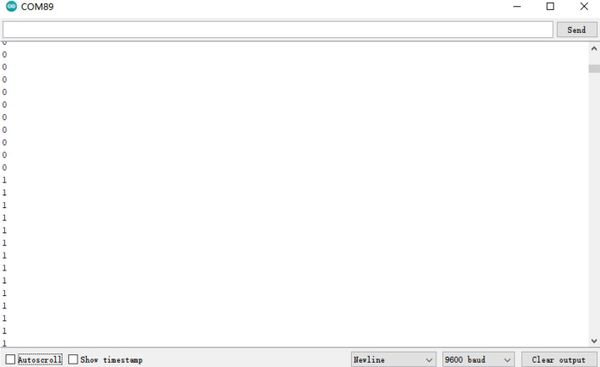
Use the arduino IDE software to upload the test code on the UNO R3 control board, connect the wires according to the wiring method, use the USB cable to power on, open the serial monitor, and set the baud rate to 9600. When the sensor detects human body movement, the D13 indicator light on the UNO R3 control board is on, and 1 is displayed on the serial monitor, otherwise the D13 indicator light on the UNO R3 control board is off, and 0 is displayed on the serial monitor; as shown below:
2. Raspberry Pi Connection Method
2.1 Put the test code (AT5820.zip) on the Raspberry Pi system and unzip it.
Raspberry Pi Test Code
#include <wiringPi.h>
#include <stdio.h>
int main()
{
  wiringPiSetup();
  char val;
  {
    pinMode(1,INPUT);
  }

  while(1)
  {
  val=digitalRead(1);
printf("OUT:%d\n",val);
  delay(100);
}
}
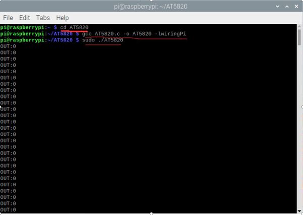
2.2 Execute the following command in the terminal to run the program. When the sensor senses human motion, the terminal outputs OUT: 1, otherwise the terminal outputs OUT: 0
cd AT5820
gcc AT5820.c -o AT5820 -lwiringPi
sudo ./AT5820
