Crash Sensor
Contents
Introduction
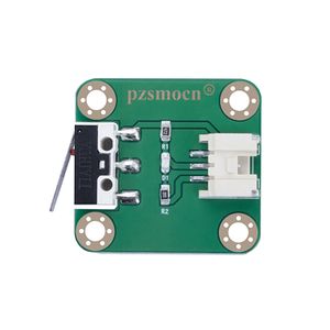
A miniature snap-action switch, also trademarked and frequently known as a micro switch, is an electric switch that is actuated by very little physical force. Micro switches are very widely used; among their applications are appliances, machinery, industrial controls, vehicles, and many other places for control of electrical circuits. They are usually rated to carry current in control circuits only, although some switches can be directly used to control small motors, solenoids, lamps, or other devices.
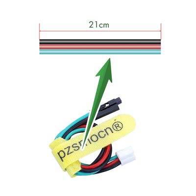
There is a press key on the sensor. During a collision, the sensor outputs a low level signal as the button is pressed, and maintains high level when released. The sensor comes with a JST PA SMT 3-Pin horizontal sticker and a buckle socket. Also, a JST PA SMT 3-Pin to DuPont female single-head wire is offered to facilitate wiring. Length: 210mm, buckle attached.
Product Size
Connection Diagram
Specifications
Sensor
- Operating Voltage: DC 3.3V-5V
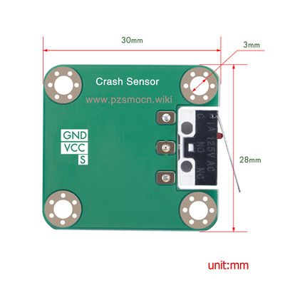
- Dimensions: 28mm * 35mm * 8.4mm
- Fixing Hole Size: 3mm
Wire
- Withstand Voltage: <50V
- Withstand Current: <1000MA
- Length: 21CM
- Wire Sequence: Black-negative power supply, Red-positive power supply, Green-signal
Demo for Arduino
int Led = 13;
int buttonpin = 3;
int val =3;
void setup() {
	pinMode (Led, OUTPUT);
	pinMode (buttonpin, INPUT);
	Serial.begin(9600);
}
void loop() {
	val = digitalRead(buttonpin);
	Serial.println(val);
	if (val == LOW) {
		digitalWrite(Led, HIGH);
	} else {
		digitalWrite(Led, LOW);
	}
}
Test Methods and Results
1. Upload the test code on the UNO R3 control board with Arduino IDE software.
2. Connect the cable according to the wiring method and power on by USB cable.
3. Turn on the serial monitor, and set the baud rate to 9600.
4. When the shrapnel of impact switch is pressed down, the D13 indicator on the UNO R3 control board is on, so is the D1 LED on the sensor, and output "0" on the serial monitor display (as shown in the picture below); Otherwise, the D13 indicator and the D1 LED are off, and output "1"on the display.
Demo for Raspberry Pi
#include <wiringPi.h>
#include <stdio.h>
int main() {
	wiringPiSetup();
	char val; {
		pinMode(1,INPUT);
	}
	while(1) {
		val=digitalRead(1);
		printf("S:%d\n",val);
		delay(100);
	}
}
Test Methods and Results
1. Save the test code as a folder in the Raspberry Pi system.
2. Execute the following commands in the terminal to run the program.
3. When the shrapnel of impact switch is pressed down, the terminal outputs "S:0", and D1 LED on the sensor is on; When released, it outputs "S:1", and the D1 LED is off.
cd TS1696
ls
gcc TS1696.c -o TS1696 -lwiringPi
ls
sudo ./TS1696


