LED RGB
Contents
Introduction
This is a common LED RGB module, in which F5 fog full-color RGB common cathode LED are used as the components. When using it, connect the RGB module to the PWM port of the microcontroller, and connect “-” to GND.
There are red, green and blue lights in the LED components. The principle is that the ratio of the three colors can be adjusted through PWM values, so that different colors of light can be displayed on the LED. In theory, all colors of light can be simulated by adjusting the ratio of the three colors.
The sensor comes with a JST PA 4P horizontal sticker and a buckle socket. Also, a JST PA SMT 4-Pin to DuPont female single-head wire is offered to facilitate wiring. Length: 210mm, buckle attached.
Product Size
Connection Diagram
Specifications
Sensor
- Operating Voltage: DC 3.3-5V
- Communication Interface: JST PA SMT 4-Pin interface
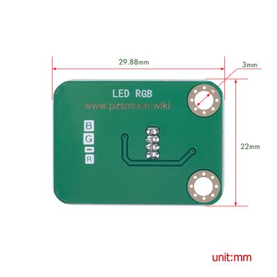
- Dimensions: 22mm * 29.88mm * 11mm
- Mounting Hole Size: 3mm
- Installation Hole Spacing: 15mm
Wire
- Withstand Voltage: <50V
- Withstand Current: <1000MA
- Length: 21CM
- Wire Sequence: Black-negative power supply, Red-positive power supply, Green-SDA, Blue-SDA
Demo for Arduino
int redPin = 9;
int greenPin = 10;
int bluePin = 11;
void setup() {
	pinMode(redPin, OUTPUT);
	pinMode(greenPin, OUTPUT);
	pinMode(bluePin, OUTPUT);
}
void loop() {
	// Basic colors:
	color(255, 0, 0);
	delay(1000);
	color(0,255, 0);
	delay(1000);
	color(0, 0, 255);
	delay(1000);
	// Example blended colors:
	color(255,255,0);
	delay(1000);
	color(128,0,255);
	delay(1000);
	color(255,255,255);
	delay(1000);
	color(0,0,0);
	delay(1000);
}
void color (unsigned char red, unsigned char green, unsigned char blue) {
	analogWrite(redPin, red);
	analogWrite(greenPin,green);
	analogWrite(bluePin, blue);
}
Test Methods and Results
First, upload the test code on the UNO R3 control board with Arduino IDE software. Then, connect the cable according to the wiring method and power on. The RGB module will successively display the following status for one second each: red, green, blue, yellow, purple, white and off, then cycle alternately.
Demo for Raspberry Pi
 #include <stdio.h>
 #include <stdlib.h>
 #include <stdint.h>
 #include <wiringPi.h>
 #include <softPwm.h>
 #include <time.h>
 #define pin_R 1
 #define pin_G 4
 #define pin_B 5
 int main(void) {
	int red,green,blue;
	if (wiringPiSetup() == -1) {
		printf("Setup GPIO error!\n");
		return -1;
	}
	softPwmCreate(pin_R, 0, 100);
	softPwmCreate(pin_G, 0, 100);
	softPwmCreate(pin_B, 0, 100);
	while (1) {
		srand((unsigned)time(NULL));
		red = rand()%101 + 0;
		green = rand()%101 + 0;
		blue = rand()%101 + 0;
		softPwmWrite(pin_R, red);
		softPwmWrite(pin_G, green);
		softPwmWrite(pin_B, blue);
		delay(100);
	}
	return 0;
}
Test Methods and Results
1. Save the test code as a folder in the Raspberry Pi system.
2. Execute the following commands in the terminal to run the program. The LED lights on the RGB module keep changing colors randomly
cd TS1697
ls
gcc TS1697.c -o TS1697 -lwiringPi
ls
sudo ./TS1697


