TCS34725 Color Sensor SKU: CQRSENYS001
Contents
Description
This module is the core color sensor of the TCS34725FN color light digitizer of ams AG. The sensor provides digital output of red, green, blue (RGB) and clear light sensing values. The integrated infrared blocking filter can minimize the infrared spectral components of the incident light, and can accurately perform color measurement. It has high sensitivity, wide dynamic range and infrared blocking filter. Minimize the effects of IR and UV spectral components to produce accurate color measurements. And with ambient light intensity detection and shieldable interrupt. Communication via I2C interface.
Specifications
Sensor Specifications
- Product Category: Light to Digital Converters/TCS34725FN
- Peak Wavelength: 525 nm
- Maximum Operating Frequency: 400 kHz
- Operating Supply Voltage: 3.3V to 5V
- Operating Current: 235 uA
- Maximum Operating Temperature: +70 Degree Celsius
- Minimum Operating Temperature: -30 Degree Celsius
- Interface Type: I2C
- Maximum Fall Time: 300 ns
- Maximum Rise Time: 300 ns
- Resolution: 4-ch RGBC, 16-bit per ch
- Recommended Measuring Distance: 20mm
- Dimension: 30.5mm * 23mm
- Mounting hole size: 3.0mm
Ocean interface Cable Specifications
- Cable Specifications: 22AWG
- Material: Silicone
- Length: 21cm
- Withstand Voltage: Less Than 50V
- Withstand Current: Less Than 1000MA
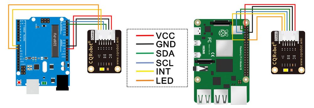
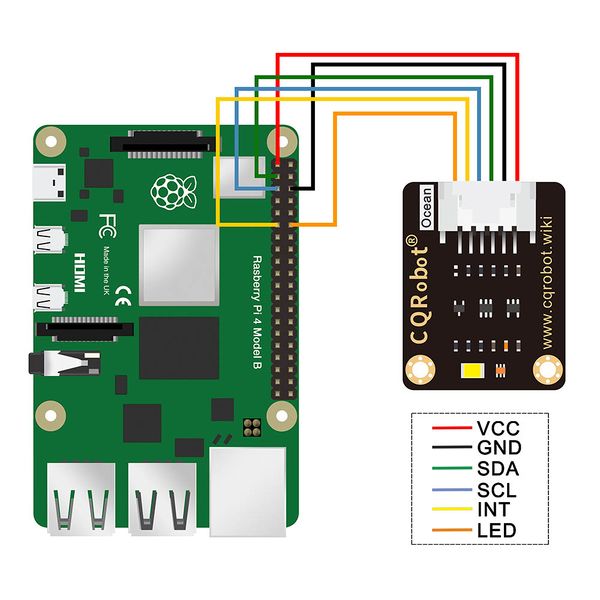
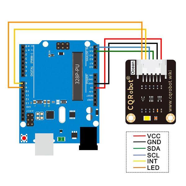
- Line Sequence: Red-Positive Power Supply; Black-Negative Power Supply; Green-I2C Data Input; Blue-I2C Clock Input; Yellow-Interrupt Output; Orange-Light Emitting Diode.
Hardware Description
Chip
TCS34725 is used for color sensing. TCS34725 is an I2C bus-based color light-to-digital converter with an IR filter, providing a digital return of red, green, blue (RGB), and clear light sensing values. The high sensitivity, wide dynamic range, and IR blocking filter make the TCS34725 an ideal color sensor solution for use under varying lighting conditions and through attenuating materials.
Communication Protocol
I2C bus has two lines, one is a data line (SDA) and another is a lock line (SDL). There are three kinds of signals when communicating, Start signal, Stop signal, and Answer signal.
- Start Signal: When SCL is High, SDA change from High to Low, it start to transmit data
- Stop Signal: When SCL is High, SDA change from Low to High, it stops transmitting.
- Answer Signal: Every time IC sends back a certain Low plus to the sender after it receives 8 bits of data.
I2C Write
When working, Raspberry Pi (hereafter named as Master) will first send a Start signal, then send a byte to TCS34725(hereafter named as Slaver), whose first 7bits are the address of Slaver and 1 bit write bit. Slave response with Answer signal every time it receives any data. Master sends command register address to Slaver, then data of command register. Stop signals are sent to slaves to stop communicating.
I2C Read
When working, Master will first send a Start signal, then send a byte to Slaver, whose first 7bits are the address of Slaver and 1 bit write bit. Slave response with Answer signal every time it receives any data. Master sends command register address to Slave. After that, Mater will send a Start signal again, and then send a byte (7bits address and 1bit read bit) to Slaver. Slaver response and send data of the register to Master, master answer as well. Stop signals will be sent to stop communicating.
I2C Address
The I2C device address of TCS34725 is 0x29
Note: 0x29 is 7bit in fact, therefore, when you set the I2C address, you should left-shift one bit, turn it to 0x52
Connection Diagram
Raspberry Pi Application
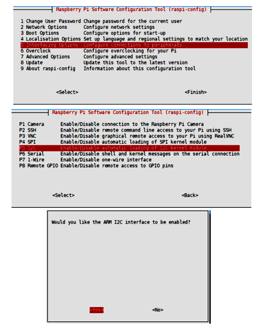
Enable I2C Interface
Open a terminal and run the following commands:
sudo raspi-config
Choose Interfacing Options -> I2C ->yes
Reboot Raspberry Pi:
sudo reboot
Install libraries
BCM2835 libraries
wget http://www.airspayce.com/mikem/bcm2835/bcm2835-1.68.tar.gz
tar zxvf bcm2835-1.68.tar.gz
cd bcm2835-1.68/
sudo ./configure && sudo make && sudo make check && sudo make install
Install wiringPi
sudo apt-get install wiringpi
wget https://project-downloads.drogon.net/wiringpi-latest.deb
sudo dpkg -i wiringpi-latest.deb
gpio -v
Python3
sudo apt-get update
sudo apt-get install python3-pip
sudo apt-get install python3-pil
sudo apt-get install python3-numpy
sudo pip3 install RPi.GPIO
sudo pip3 install spidev
Download examples
Open a terminal of the Raspberry Pi
sudo apt-get install p7zip-full -y
sudo wget https://www.waveshare.com/w/upload/a/a1/TCS34725_Color_Sensor_code.7z
7z x TCS34725_Color_Sensor_code.7z -O./TCS34725_Color_Sensor_code
cd TCS34725_Color_Sensor_code/RaspberryPi/
Hardware Connection
Download and Run the Test Examples
Media: TCS34725 Color Sensor-Raspberry Pi.rar
Run Examples
C examples
cd ~/TCS34725_Color_Sensor_code/RaspberryPi/
cd wiringPi
sudo make clean
sudo make
sudo ./main
Python example
cd ~/TCS34725_Color_Sensor_code/RaspberryPi/
cd python
sudo python main.py
Expected result
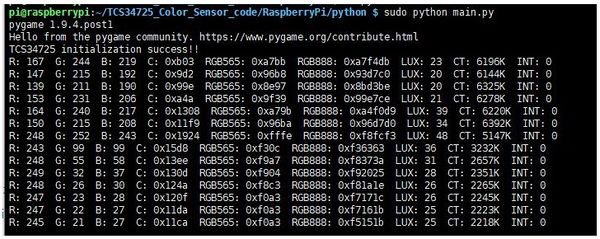
The RGB data are printed in terminal:
R, G, B values are printed in RGB888 format (DEC), C is light value without processing, RGB565 and RGB888 are HEX data printed in a certain format. LUX is light value processed. CT is color temperature. (https://en.wikipedia.org/wiki/Color_temperature) If you want to measure CT, please turn off the LED. INT is interrupted, 1: light value is over the threshold.
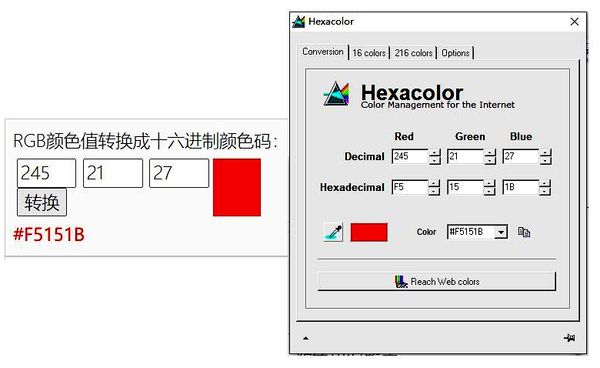
You can turn the RGB value to color with tools:
Media: TCS34725 Color Sensor Tool-Raspberry Pi.rar
Arduino Application
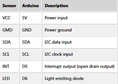
The Arduino example is written for the Arduino UNO. If you want to connect it to other Arduino boards, you may need to change the connection.
Hardware Connection
Download and Run the Test Examples
Media: Adafruit_TCS34725-1.4.4.zip
Examples
- Install the Arduino IDE in your PC
- Install the library file into Arduino IDE (select the compressed file named Adafruit_TCS34725-1.4.4_Arduino.zip downloaded before the tutorial and click "Confirm" Note: It must be a compressed file in zip format, do not unzip it)
- Use the library file routine for verification (choose one, the tutorial takes "tcs34725" as an example).
- Choosing the Right Motherboard and Ports.
- Upload to the development board.
- Open the serial monitor of Arduino IDE and check the serial port data.
- Experimental results:
The serial monitor outputs six parameters: color temperature, light intensity, red light intensity, green light intensity, blue light intensity, and transparent light flux.
- A summary of the specific meaning of each value.
STM32 Application
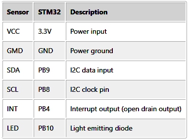
The STM32 examples are based on the STM32F103RBT6 and the STM32H743. The connection provided below is based on the STM32F103RB. If you need to use other STM32 boards, you may need to change the hardware connection and port the code yourself.
Hardware Connection
Download and Run the Test Examples
Media: TCS34725 Color Sensor-STM32.rar
Examples
The examples are developed based on the HAL libraries. Download the Demo codes archive to your PC. Unzip and find the STM32 project from TCS34725_Color_Sensor_code\STM32\XNUCLEO-F103RB\MDK-ARM.
- Open the TCS34725_Color_Sensoc.uvprojx file by Keil
- Build and the project
- Program the project to your STM32 board.
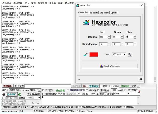
- Connect the UART1 of your STM32 board to the PC and check the serial data by SSCOM software.
R, G, B values are printed in RGB888 format (DEC), C is light value without processing, RGB565 and RGB888 are HEX data printed in a certain format. LUX is light value processed. CT is color temperature. (https://en.wikipedia.org/wiki/Color_temperature) If you want to measure CT, please turn off the LED. INT is interrupted, 1: light value is over the threshold.
You can turn the RGB value to color with tools:
Media: TCS34725 Color Sensor Tool-STM32.rar
FAQ
1,Question:
Whiy does the data are all be 0?
Answer:
Please check if you connect the correct pins.
2,Question: All the RGB data output is 253 as the picture.
Answer:
In this case, the light intensity exceeds the inspection range, and reducing the gain can solve the problem (modify in the initial, or rewrite the gain setting TCS34725_Set_Gain(TCS34725_GAIN_16X) after the initialization).
3, Question:
The color is abnormal after changing the integration time?
Answer:
Because the integration time determines the maximum value of the RGBC channel data, modifying the integration time will result in darker or whiter colors. Just need to increase or decrease the brightness of the LED.
4,Question:
Modifying the integration time cannot trigger an interrupt or keep repeating the interrupt?
Answer:
The interrupt is compared with the data in the Clear channel. The data in the Clear channel is related to the integration time. After actual measurement, the gain is 60 times.
Therefore, you should modify the threshold value if sample rate is fast. And please increase brightness of LED when you set integrate time to 2.4ms.


