TSL25911 Digital Ambient Light Sensor SKU: CQRSENHJ001
Contents
Description
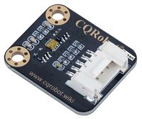
This is a high sensitivity digital ambient light sensor module based on TSL25911, features 600M:1 wide dynamic range, detects light intensity up to 88000Lux, controlled via I2C interface, low power consumption. It is capable of operating across various light environment.
Specifications
- Light sensor: TSL25911FN
- Communication interface: I2C (constant address: 0x29)
- Effective range: 0 to 88000Lux (Bright Sunlight)
- Operating voltage: 3.3V/5V
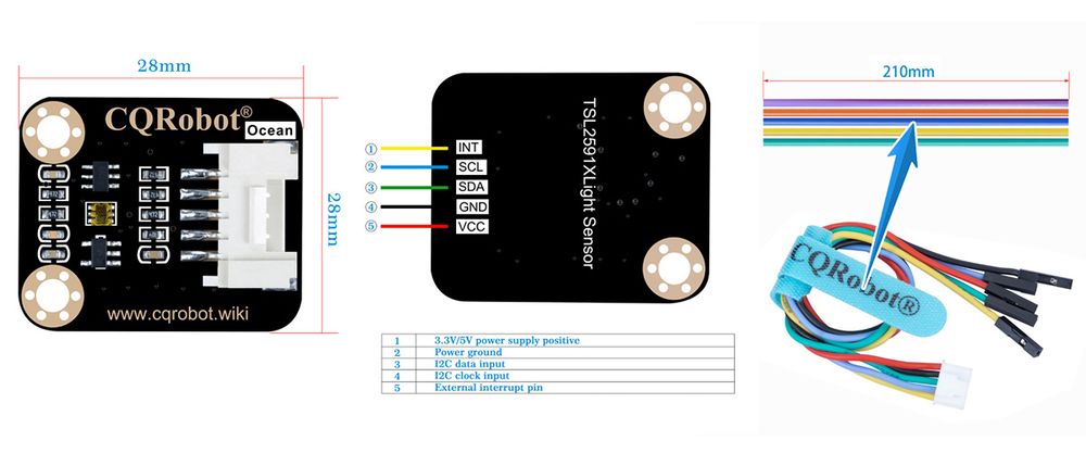
- Dimensions: 28mm * 28mm
- Mounting hole size: 3.0mm
Ocean Interface Cable Specifications
- Cable specifications: 22AWG
- Material: Silicone
- Withstand Voltage: Less Than 50V
- Withstand Current: Less Than 1000MA
- Length: 21cm
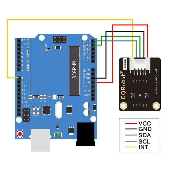
- Line Sequence: Black-Negative Power Supply, Red-Positive Power Supply, Green-SDA, Blue-SDA, Yellow-INT.
Hardware Description
Chip
This product uses TSL25911FN, which is a light intensity digitizer based on IIC bus communication. The sensor combines a wideband photodiode (visible and infrared) and an infrared response photodiode on a single CMOS integrated circuit that provides near-light adaptive response over an effective 16-bit dynamic range (16-bit resolution). Two integral ADCs convert the photodiode current into a digital output representing the irradiance measured on each channel. The digital output can be inputted to a microprocessor where an empirical formula is used to derive illuminance in lux (ambient light level) to approximate the human eye response.
Timing analysis
TSL2591 use I2C interface, has a data line and a clock signal line. There are three types of signals will be used during the I2C bus data transmissing. They are Start signal, Stop signal, and Ack signal.
Start signal: When SCL is HIGH and SDA jumps from HIGH to LOW, the data transmission starts. Stop signal: When SCL is HIGH and SDA jumps from LOW to HIGH, the data transmission stops. Ack signal: When the receiver IC have received 8 bit of data, it will send out a special LOW level pulse to the transmitter IC to indicate that the data have been received.
I2C Write
At the beginning, the Host sends out a start signal, and combines the 7 bit of I2C slave address with the Write bit, then, sends this 8 bit of data to the Slave. Then, the Slave sends back an ACK signal when it has received the data. The Host transmits the slave address of the command register to the Slave as soon as it received the ACK signal. And the Slave responds an ACK signal when it has received the slave address. At this moment, the Host sends out a start signal once again, and combines its 7 bit of slave address with Read bit, then, sends this 8 bit data to the Slave. And then, the Slave responds an ACK signal to the Host when it has received the data, and sends out the data stored in the Slave register to the Host. The Host sends back an ACK signal as soon as it received the value. The I2C communication will be continued, till the Host sends out a stop signal.
I2C Read
At the beginning, the Host sends out a start signal, and combines the 7 bit of I2C slave address with the Write bit, then, sends this 8 bit of data to the Slave. Then, the Slave sends back an ACK signal when it has received the data. The Host transmits the slave address of the command register to the Slave as soon as it received the ACK signal. And the Slave responds an ACK signal when it has received the slave address. At this moment, the Host sends out a start signal once again, and combines its 7 bit of slave address with Read bit, then, sends this 8 bit data to the Slave. And then, the Slave responds an ACK signal to the Host when it has received the data, and sends out the data stored in the Slave register to the Host. The Host sends back an ACK signal as soon as it received the value. The I2C communication will be continued, till the Host sends out a stop signal.
I2C Address
The I2C address of the TSL25911 is as follows:0x29
P28 of the TSL25911 datasheet
Note: The device address of 0x29 is 7 bits, and the 8-bits device address required to be shifted to 0x52 by moving 1 bit to high position.
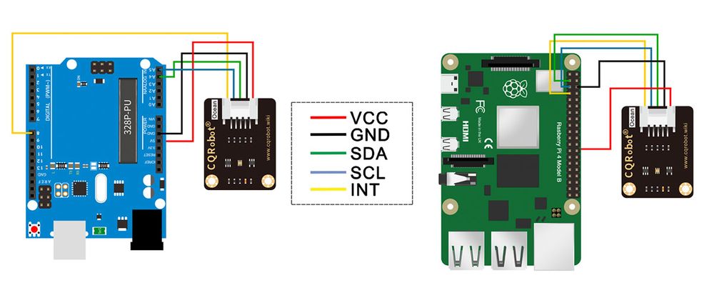
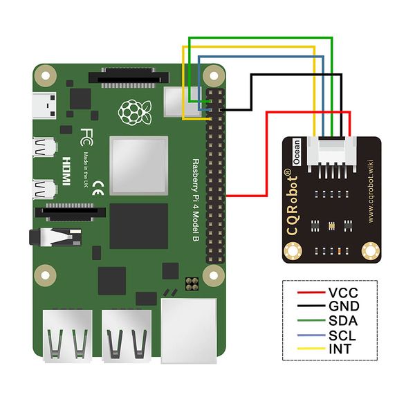
Connection Diagram
Raspberry Pi Application
Open the I2C
- Open the terminal and execute the code as follow :
 sudo raspi-config
 Select Interfacing Options -> i2c-> yes to start the I2C  driver
- Then restart Raspberry Pi:
sudo reboot
Install libraries
- Install BCM2835 libraries
 wget http://www.airspayce.com/mikem/bcm2835/bcm2835-1.60.tar.gz
 tar zxvf bcm2835-1.60.tar.gz
 cd bcm2835-1.60/
 sudo ./configure
 sudo make
 sudo make check
 sudo make install
 # For more code, please refer to our official website http://www.airspayce.com/mikem/bcm2835/
- Install wiringPi libraries
 sudo apt-get install wiringpi
 #For Raspberry Pi 4B, an upgrade may be required:
 cd /tmp
 wget https://project-downloads.drogon.net/wiringpi-latest.deb
 sudo dpkg -i wiringpi-latest.deb
 gpio -v
 #Running gpio -v will appear version 2.52. If not, the installation is wrong.
Hardware Connection
| TSL25911 Light Sensor | Raspberry Pi(BCM) |
| VCC | 3.3V |
| GND | GND |
| SDA | SDA(2) |
| SCL | SCL(3) |
| INT | 4 |
Download and run the test examples
Media: TSL25911 Ambient Light Sensor-RaspberryPi.rar
 sudo apt-get install p7zip-full
 7z x TSL2591X_Light_Sensor_code.7z -r -o./TSL2591X_Light_Sensor_code
 sudo chmod 777 -R  TSL2591X_Light_Sensor_code
- C code
 cd c
 make clean
 make
 sudo ./main
- Python code
 cd python
 sudo python main.py
STM32 Application
Download the example from Waveshare Wiki and unzip it. The STM32 projects are located at the path ~/STM32/… Open \XNUCLEO-F103RB\MDK-ARM\demo.uvprojx project with Keil uVision5.
The example is based on HAL library. The development board used for the test is XNUCLEO-F103RB of Waveshare, wich chip is STM32F103RBT6.
If you want to port the examples for other STM32 chip, or change to standard libraries, you can only modify the DEV_Config.c and .h files to implement the functions and acro definitions. You can also use STM32CubeMX to port example. The example uses UART3 (PA3, PA3) to output debug information. It is set to 115200, 8N1.
Hardware connection
The connection is shown in the following table:
| TSL25911 Light Sensor | STM32 |
| VCC | 3.3V |
| GND | GND |
| SDA | SDA/D14/PB9 |
| SCL | SCL/D15/PB8 |
| INT | D8/PA9 |
Download and run the test examples
Media: TSL25911 Ambient Light Sensor-STM32.rar
Expected Result
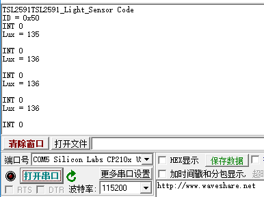
Open the serial port assistant software on the computer and select the corresponding port to check the output data:
Arduino Application
Download the example from Waveshare Wiki and unzip it. The Arduino projects are located at the path ~/Arduino/…
Copy the folder in the Arduino directory to the library in the Arduino installation directory.
Open the Arduino IDE: Click File-> Example to see if there is a TSL25911 option.
If so,the library is imported successful, open TSL25911-demo, select the corresponding COM port, download it to UNO, open the serial monitor, and check the data outputed.
Hareware connenction
| TSL25911 Light Sensor | Arduino |
| VCC | 3.3V/5V |
| GND | GND |
| SDA | SDA |
| SCL | SCL |
Download and run the test examples
Media: TSL25911 Ambient Light Sensor-Arduino.rar
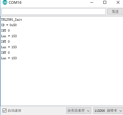
Expected result
The figure below shows the data of the test:
FAQ
1,Question:
What happens if the Raspberry Pi is applied incorrectly??
Answer:
If the example of running the wiringPi are normal, then running python or BCM2835 may refresh the screen abnormally,Because the library of bcm2835 is the library function of the Raspberry Pi cpu , operating register directly.And the bottoms of the wiringPi library and python are to read and write linux system device files to opera devices ,which may cause the GPIO port to be abnormal.Restart the Raspberry Pi to solve the problem perfectly.
2,Question:
STM32 and Arduino examples serial output has no data or data output garbled?
Answer:
Make sure that is it the baud rate set to 115200? For the STM32 examples, make sure that the computer is connected to the development board USART2 (PA2, PA3) properly , PA2 is TXD. And select the correct COM port:Control Panel -> Hardware -> Device Manager. |}
3,Question:
The output data of the examples is 0 or the initialization failed ? |}
Answer:
Please check the connection of the pins..
